NCTUCS 2013-Fall Computer Organizaion by …
NCTUCS 2013-Fall Computer Organizaion by Professor Kai-Chiang Wu
Ch4 - The Processor
Introduction
- CPU performance factor
- Instrction count: Determined by ISA and compiler
- CPI and Cycle Time: Determined by CPU hardware
- Two MIPS example
- Simple subset, shows most aspects
- Memory reference: lw, sw
- Arithmetic/logical: add, sub, and, or, slt
- Control transfer: beq, j
Instruction Execution
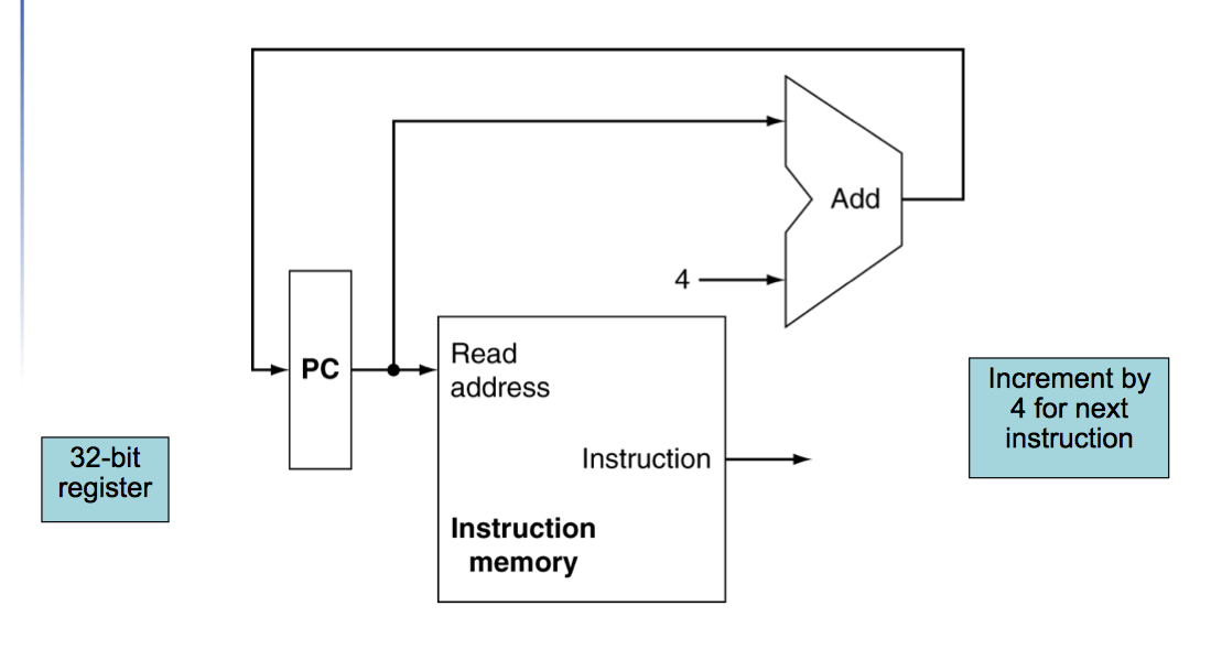
- PC, instruction memory, fetch instruction
- Register numbers, register file, read registers
- Depending on instruction class
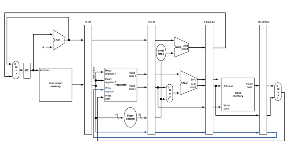
CPU Overview
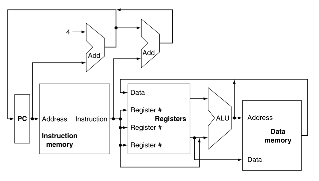
Mutiplexers
You should use MUX to join wires together.
Control
RegWrite, RegRead, MUX, MemRead, MemWrite, Zero, ALU operation, Branch
Logic Design Basic
- Information encoded in binary
- Low voltage = 0, High voltage = 1
- One wire per bit
- Multi-bit data encoded on multi-wire buses
- Combinational element
- Operate on data
- Output is a function of input
- State (sequential) elements
- Store information
Combinational Elements
AND gate, Adder, MUX, ALU
Sequential Elements
- Register: stores data in circuit
- Uses a clock signal to determine when to update the stored value
- Edge-triggered: update when Clk changes from 0 to 1
Performance Issues of Single Cycle Design
- Longest delay determines clock period
- critical path: load instruction
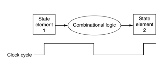
Clocking Methodology
- Combinational logic transforms data during clock cycles
- Between clock edges
- Input from state elements, output to state element
- Longest delay determines clock period
Building a Datapath
Datapath: Elements that process data and addresses in the CPU. ex: Reg, ALU, MUX, Mem
Instruction Fetch
R-Format Instructions
- Read two register operands
- Perform arithmetic/logical operation
- Write register result
Load/Store Instructions
- Load: Read memory and update register
- Store: Write register value to memory
- Read register operands
- Calculate address using 16-bit offset
- Use ALU, but sign-extend offset
Hazards
Situations that prevent starting the next instruction in the next cycle
Structure Hazards
- Conflict for use of a resource
- In MIPS pipeline with a single memory
- Load/store requires data access
- Instruction fetch would have to stall for that cycle
- Would cause a pipeline “bubble”
- Pipelined datapaths require separate instruction/data memories or separate instruction/data caches
Data Hazards
An instruction depends on completion of data access by a previous instruction
-
Forwarding (aka Bypassing)
- Use result when it is computed
- Don’t wait for it to be stored in a register
- Requires extra connections in the datapath
-
Load-Use Data Hazard
- Can’t always avoid stalls by forwarding
- If value not computed when needed
- Can’t forward backward in time!
- Can’t always avoid stalls by forwarding
-
Code Scheduling to Avoid Stalls
- Reorder code to avoid use of load result in the next instruction
Control Hazards
- Branch determines flow of control
- Fetching next instruction depends on branch outcome
- Pipeline can’t always fetch correct instruction
In MIPS pipeline
Need to compare registers and compute target early in the pipeline
Add hardware to do it in ID stage
- Stall on Branch
- Wait until branch outcome determined before fetching next instruction
Branch Prediction
Pipeline Summary
-
Pipelining improves performance by increasing instruction throughput
- Executes multiple instructions in parallel
- Each instruction has the same latency
-
Subject to hazards
- Structure
- Data
- Control
-
Instruction set design affects complexity of pipeline implementation

MIPS Pipelined Datapath
From left to right:
- IF: Instruction fetch
- ID: Instruction decode / register file read
- EX: Execute / address calculation
- MEM: Memory Access
- WB: Write Back
left to right flow leads to hazards
Pipeline Registers
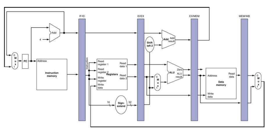
- Need registers between stages to hold information produced in previous cycle.
- IF and ID are in different instruction cycle, so we need registers.
- If some results in this stage won't be used in the next stages, we don't need store those results in the pipeline registers.
Pipeline Operation
Cycle-by-cycle flow of instructions through the pipelined datapath
-
“Single-clock-cycle” pipeline diagram
- Shows pipeline usage in a single cycle
- Highlight resources used
-
“multi-clock-cycle” pipeline diagram
- Graph of operation over time
Corrected Datapath for Load
write address should be stored in the pipeline registers.
Forwarding Paths
- Forwarding Unit
- Control Unit
Forwarding Conditions
// EX hazard
if (EX/MEM.RegWrite && (EX/MEM.RegisterRd != 0))
{
    if (EX/MEM.RegisterRd = ID/EX.RegisterRs) ForwardA = 10;
    if (EX/MEM.RegisterRd = ID/EX.RegisterRt) ForwardB = 10;
}

// MEM hazard
if (MEM/WB.RegWrite && (MEM/WB.RegisterRd != 0))
{
    if (MEM/WB.RegisterRd = ID/EX.RegisterRs) ForwardA = 01;
    if (MEM/WB.RegisterRd = ID/EX.RegisterRt) ForwardB = 01;
}
Double Data Hazard
add $1,$1,$2
add $1,$1,$3
add $1,$1,$4
- Both hazards occur -> Want to use the most recent
- Revise MEM hazard condition -> Only fwd if EX hazard condition isn’t true
Revised Forwarding Condition
// MEM hazard
if (MEM/WB.RegWrite && (MEM/WB.RegisterRd != 0))
{
    if ( !(EX/MEM.RegWrite && (EX/MEM.RegisterRd != 0)
    && (EX/MEM.RegisterRd = ID/EX.RegisterRs)) )
    {
        if (MEM/WB.RegisterRd = ID/EX.RegisterRs) ForwardA = 01;
    }

    if ( !(EX/MEM.RegWrite && (EX/MEM.RegisterRd != 0)
    && (EX/MEM.RegisterRd = ID/EX.RegisterRt)) )
    {
        if (MEM/WB.RegisterRd = ID/EX.RegisterRt) ForwardB = 01;
    }
}
Load-Use Hazard Detection
# Load-use hazard happens when
ID/EX.MemRead and
((ID/EX.RegisterRt = IF/ID.RegisterRs) or (ID/EX.RegisterRt = IF/ID.RegisterRt))
- Check when using instruction is decoded in ID stage
- If detected, stall and insert bubble
- 對一個 load word 的指令來說,我們要看的是他的 Rt
How to Stall the Pipeline
- Force control values in ID/EX register to 0
- EX, MEM and WB do nop (no-operation)
- Prevent update of PC and IF/ID register
- Using instruction is decoded again
- Following instruction is fetched again
- 1-cycle stall allows MEM to read data for lw
Stalls and Performance
- Stalls reduce performance
- But are required to get correct results
- Compiler can arrange code to avoid hazards and stalls
- Requires knowledge of the pipeline structure
Reducing Branch Delay
- Move hardware to determine outcome to ID stage
- Target address adder
- Register comparator
- Example: Branch taken
把 branch 決定的時間從 stage4 提早到 stage2,
在 stage2 才會知道這個 branch 是否會被 taken
決定的時間越早越好, 最早就是在 stage2 決定
Data Hazards For Branches
If a comparison register is a destination of
+ 2nd or 3rd preceding ALU instruction
+ Can resolve using forwarding
+ preceding ALU instruction or 2nd preceding load instruction
+ Need 1 stall cycle
+ immediately preceding load instruction
+ Need 2 stall cycles
Dynamic Branch Prediction
NOTE
- Intel Sandy Bridge 的 pipeline 約有 17 個 stage
- Intel Sandy Bridge 和 Ivy Bridge 是以色列的研發團隊研發的
- Haswell 是美國團隊研發的
Share
Donation
如果覺得這篇文章對你有幫助, 除了留言讓我知道外, 或許也可以考慮請我喝杯咖啡, 不論金額多寡我都會非常感激且能鼓勵我繼續寫出對你有幫助的文章。
If this blog post happens to be helpful to you, besides of leaving a reply, you may consider buy me a cup of coffee to support me. It would help me write more articles helpful to you in the future and I would really appreciate it.